
Getting started with the SODA HE 1.0
|
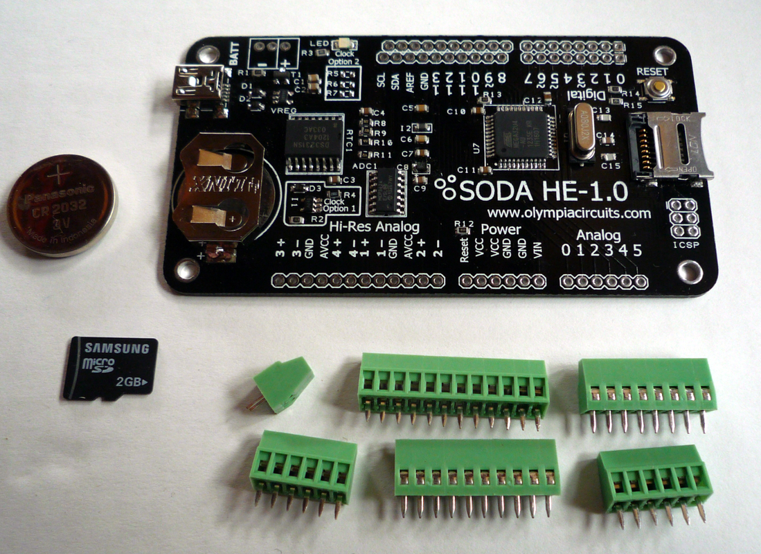
The SODA HE 1.0 comes with screw terminal headers, a 2 GB microSD card and a coin cell battery.
|
|
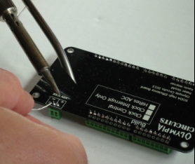
Step 1. Solder Headers
Screw terminals are recommended for datalogging as they provide much more reliable connections to sensors and batteries than the standard headers used by Arduino boards. They reduce the frustration of having wires pop out at the wrong time. Make sure you face the headers in the right direction before you start soldering. The "mouth" of each header is easy to see and should point towards the outside of the board.
The HE 1.0 has two sets of terminals on the digital pin side. The inner set of pins are spaced in intervals of 0.1 inch and don't have the "custom" spacing of the standard Arduino layout. Male headers can be soldered to these terminals to allow the board to be placed in a solderless breadboard. I recommend soldering screw terminals (if you use them) to these inner set of pins since they provide a little more support than the outer set.
The footprint of the HE 1.0 is compatible with the standard Arduino layout. If you needed to use a shield you can solder standard headers on the outer set of terminals. Note that the HE 1.0 uses the same layout as the Arduino Leonardo and the hardware I2C pins are in different locations than the Uno and other Arduino boards. This has caused some problems with shields that use I2C and were designed for the Uno. You have two options in you want to use a shield with the standard I2C pins: 1) use software I2C instead of hardware (requires an extra library) or 2) solder jumper wires to connect the "Leonardo" pins to the "Uno" pins (SDA Pin: 2 -> A4; SCL Pin: 3 -> A5).
|
|
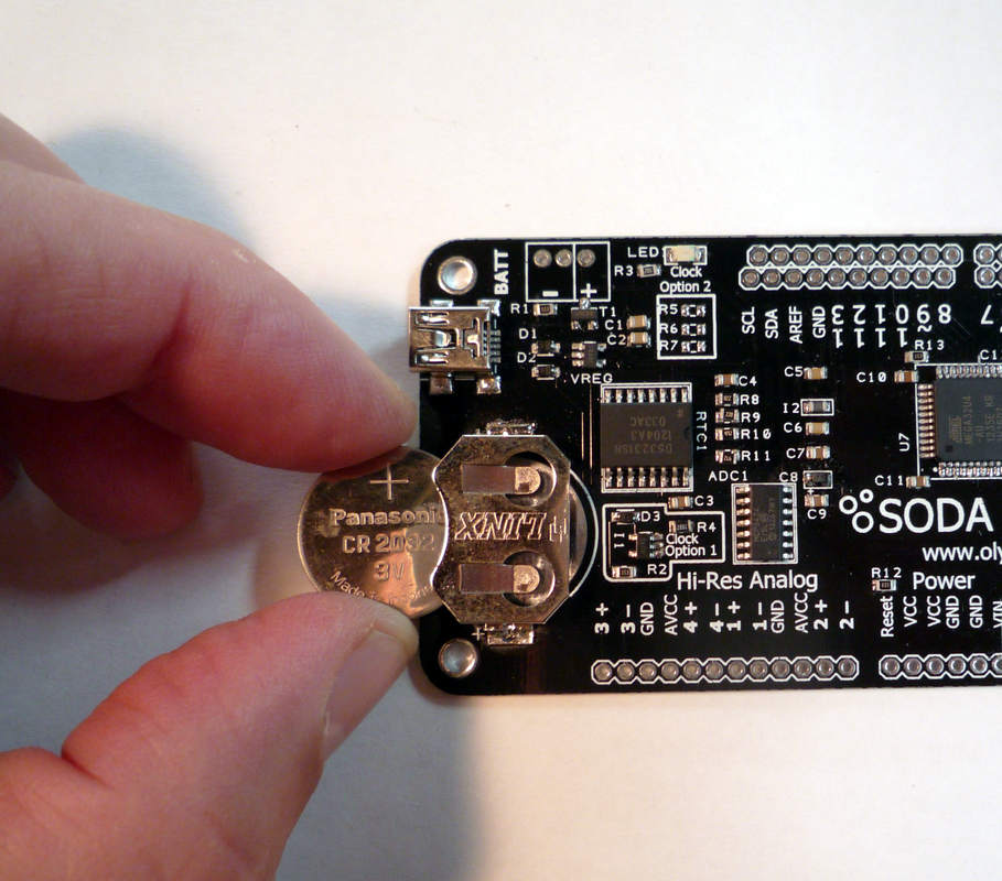
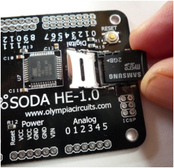
Step 2. Install the coin cell battery and SD card
This is pretty simple. The battery goes in with the + side up. The SD card terminal unlocks by sliding it to the left (while holding the board with the SD card terminal on the right) and locks again by closing it and sliding it to the right. Make sure the SD card is seated properly in the terminal.
This is pretty simple. The battery goes in with the + side up. The SD card terminal unlocks by sliding it to the left (while holding the board with the SD card terminal on the right) and locks again by closing it and sliding it to the right. Make sure the SD card is seated properly in the terminal.
|
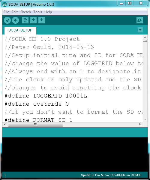
Step 3. Set the clock and LOGGERID
After installing the SODA library in the Arduino library folder, you can find the SODA_SETUP program under the File > Examples tab in the Arduino IDE. The program does three things: 1) It sets the HE 1.0 clock using the current time on your computer. With the coin cell battery installed you can set the clock and it will keep time even when the board is removed from its power source 2) It saves an ID number in the chip's nonvolatile memory. You select the number but each logger you use should have a different number. The LOGGERID is used to link your data back to the datalogger installation. 3) It formats the SD card in FAT16 format. This format can be read and written by both the SODA HE 1.0 and PCs. |
|
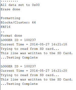
Once you upload the setup program you can switch to the serial monitor to make sure everything worked. You might catch some output from the SD formatting operation. Once everything is done you will see the LOGGERID, current time, and a test of the SD card. You should see "This line was written to the SD Card." If you don't, there's a problem. Make sure the SD card is seated properly and try it again. Also, try waiting about ten seconds after uploading to switch to the serial monitor. It seems like switching to the serial monitor too quickly can sometimes disrupts the SD card formatting.