
Setting up your LeOlympia
The board ships with the Leonardo bootloader that is supplied with Arduino 1.0.1. The LeOlympia acts like a Leonardo, check out the Arduino Leonardo Guide for setup details: http://arduino.cc/en/Guide/ArduinoLeonardo
Use the Arduino IDE release 1.0.1. The board works with the Leonardo board profile.
Use the Arduino IDE release 1.0.1. The board works with the Leonardo board profile.
Using the aux input button
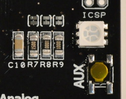
The AUX input button is located next to the RGB LED. It is a simple, normally open, pushbutton switch. The internal pullup resistor must be used with the switch. To use include this code in your sketch:
pinMode (12,INPUT);
digitalWrite (12, HIGH);
pinMode (12,INPUT);
digitalWrite (12, HIGH);
Using the integrated RGB LED
The RGB LED is the small, white, square component seen in the picture above. The pins are as follows:
Red = pin 9
Green = pin 10
Blue = pin 11
The LED has integrated resistors that limit current to 20mA per LED. The LEDs can be used as on/off or with PWM to create a range of colors.
WARNING: This is a clear lens LED, don't look directly at it. The light output is very bright and focused.
The bright light allows you to diffuse the light in a way that fits your project. We've tried shining through white acrylic, into a ping pong ball and onto a white surface. Once it's indirect it is well mixed, pleasing light.
Disabling the RGB LED
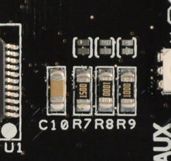
There are three solder jumpers on the board to allow you to disconnect the RGB LED from the circuit. They are located next to the LED's dropping resistors. To disable the LED, scratch the trace between the solder pads. To re-enable, bridge the gap with solder.
Examples
RGB Fade
nunchuck pan tilt
nunchuck pan tilt
Power Header Silkscreen
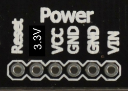
There is an error on the silkscreen on the first batch of boards. The pins are connected the same as an Arduino, with both 3.3V and 5V (Vcc), but two pins are labelled as VCC. See picture here for correct marking.
Leonardo Pin Functions
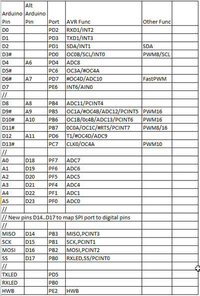
While the primary pin functions remain the same as an UNO, some secondary functions like interrupts and SDA/SCL have moved. This chart shows the pins' functions.
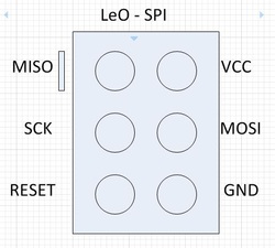
LeOlympia and Leonardo - SPI
SPI and I2C pins changed between Uno and Leo boards. See the image at left for SPI pins on the ICSP header for the LeOlympia. I believe the Leonardo has same pinout, but haven't pulled up board file.
SPI and I2C pins changed between Uno and Leo boards. See the image at left for SPI pins on the ICSP header for the LeOlympia. I believe the Leonardo has same pinout, but haven't pulled up board file.
| leonardo_pin_functions.xlsx |