The HE 1.0: High-Resolution ADC
Not all measurements are created equal. This can be a difficult concept to grasp. We often see measurements and don't ask where they came from, but it's important to understand the precision of a given measurement. Imagine measuring the height of a person with a device that only returns values to the nearest meter. Now use a second and third device that measure to the nearest 0.1 meter and 0.01 meters. You might end up with the following measurements: 2, 1.6, 1.56. Each level of precision gives you more information on the real value.
Many signals in datalogging are measured in volts using an analog-digital converter (ADC). The ADC does the important job of turning a real-world measurement into a digital value. There are different types of ADCs. The differences among them can be viewed in terms of their reference voltage and resolution. The ATmega32U4 chip (and other Arduino chips) has a built-in ADC with a reference voltage equal to the rail voltage (3.3V on the HE 1.0) and a resolution of 10 bits. The 10 bits divide the reference voltage into bins (like the device we used to measure height). With 10 bits we get 1024 bins (2 to the 10th power) and each bin is 3.3 V / 1024 = 0.0032 volts or 3.3 mV. So a real-world voltage of 1.001 and 1.003 volts would end up in the same bin. This is fine if the signal is large relative to the reference voltage but not good if we need to know the difference between 1.001 and 1.003 V or the signal is small in general.
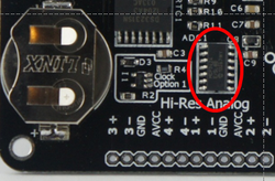
In many cases we want to measure a voltage signal with greater precision. The MCP3424 ADC on the HE 1.0 has a resolution of up to 18 bits and a reference voltage of 2.048 V. Measurements are made in the SODA library using the adcRead command. In addition to making high resolution measurements, the MCP3424 makes differential or two-end measurements. The ADC in the Arduino chip can only measure a difference in voltage between ground and a device. A differential measurement is the differences between two points on a circuits; both points could have voltages above ground. Additionally, the MPC3424 measures between -2.048 V and + 2.048 V. The ability to measure negative differential voltages is important for many sensors.
