SODA HE 1.0 Power Management
Power management is an important consideration when deploying dataloggers since they typically need to run for long periods of time from battery power. Standard Arduino boards do a very poor job of managing power. They draw considerable current from their batteries even when the microcontroller is in sleep mode. The culprit is the quiescent current drawn from the voltage regulator, which is the current drawn even when there's no load. This baseline current draw is even greater if you add an SD card or other devices that are not powered through the microcontroller.
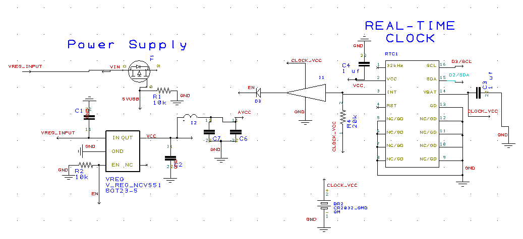
The HE 1.0 board gets around the problems associated with power management by shutting off the entire board, other than the real-time clock, between measurements. This is done by using a voltage regulator with an enable pin and linking it to the alarm pin of the real-time clock. When the clock alarm is engaged, the alarm pin goes low. The signal passes through an inverter which pulls the voltage regulator pin high, thereby enabling the voltage regulator and powering up the rest of the board. The real-time clock is powered by the extra CR2032 battery while the rest of the board is turned off. The power circuit also has a bypass so that the board powers up when attached to USB. Here's a screen shot of the schematic:
The HE 1.0 board gets around the problems associated with power management by shutting off the entire board, other than the real-time clock, between measurements. This is done by using a voltage regulator with an enable pin and linking it to the alarm pin of the real-time clock. When the clock alarm is engaged, the alarm pin goes low. The signal passes through an inverter which pulls the voltage regulator pin high, thereby enabling the voltage regulator and powering up the rest of the board. The real-time clock is powered by the extra CR2032 battery while the rest of the board is turned off. The power circuit also has a bypass so that the board powers up when attached to USB. Here's a screen shot of the schematic:
The stingy power management of the HE 1.0 should allow the board to be powered by three AA batteries for years under typical conditions.
One thing to remember when connecting the HE 1.0 to a battery is that it won't turn on right away unless the alarm on the real-time clock has already been triggered. This can be a bit of a surprise. When testing a set up you might set the board to record at 10 second intervals so you can see that everything is working. The LED on the upper-left of the board will blink when the SD card is being written to let you know when data are recorded.
We built-in the option of configuring the HE 1.0 to run more like a regular Arduino board without the clock control. Let us know if you'd like some built that way. If you want the regular board to stay on you can either trigger an alarm and not reset it or power it through the USB connector.

