
DS18B20 Temperature Sensors
The DS18B20 is a a digital, addressable temperature sensor that is popular in the Arduino world. As a digital sensor, it produces direct readings without the need to calculate the actual temperature from a voltage reading. It has a temperature range of -55 C to 125 C with an accuracy of 0.5 degrees. As an addressable sensor, it can be placed on a bus which means that multiple sensors can be attached to the same input pin. Each sensor has a unique address that's used to call that sensor and retrieve a reading while the other sensors remain silent, waiting their turns.
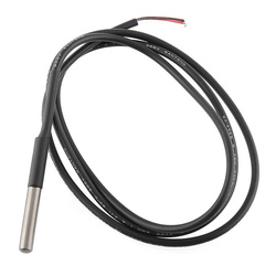
You can get the DS18B20 in through-hole and surface mount packages. There are also many, many suppliers selling the sensor in a stainless steel enclosure with a cable like the one picture here. These are advertised as waterproof and it seems believable though I actually haven't tried to submerge one for a long period of time.
The sensor can work is parasitic power mode which means that it only requires two wires: a data wire and a ground. Power is pulled from the data pin. I've used it this way and it works. The data pin requires a pull-up resistor; most people use 4.7 K between the data pin and rail voltage. The internal pullups in the Atmel chips are too weak so an external resistor is needed.
The sensor can work is parasitic power mode which means that it only requires two wires: a data wire and a ground. Power is pulled from the data pin. I've used it this way and it works. The data pin requires a pull-up resistor; most people use 4.7 K between the data pin and rail voltage. The internal pullups in the Atmel chips are too weak so an external resistor is needed.
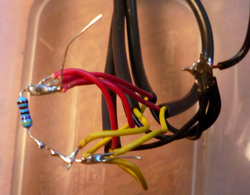
In this example I attach four DS18B20s to a single digital pin in a bus configuration. To make attaching the pins to the SODA screw terminals easiers, I soldered all of the data wires to on end of a 4.7k resistor and all of the power wires to the other end. I used regular power mode instead of parasitic power. All of the ground wires were soldered together as well.
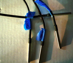
The bus configuration does present the problem of figuring out sensor is which. I used the .requestTemperatures() method in the DallasTemperature library which calls sensors sequentially based on their ID numbers, but the sensors themselves are not marked. I simply put each one in my hand and noted which temperature increased (it's fairly cold in my shop) and then labeled them sequentially.
The program was a simple datalogging program with an additional function to load the temperature readings into an array. The oneWire and DallasTemperature libraries were used to communicate with the sensors.
#include <OneWire.h>
#include <DallasTemperature.h>
#include <EEPROM.h>
#include "SODA.h"
#include <SdFat.h>
#include <Wire.h>
SODA soda;
float temp[4];
int num_sensors = 4;
void setup(){
soda.begin();
pinMode(1,OUTPUT);
pinMode(4,INPUT);
digitalWrite(1,HIGH);
}
void loop(){
soda.communicate();
getDS18B20(4,4,temp);
soda.dataLineBegin();
for(int k = 0; k<num_sensors; k++){
soda.dataLineAdd(temp[k]);
}
soda.dataLineEnd();
soda.setWake(10,2);
soda.turnOff();
}
/////////////////////////////////////////////////////////////////////////////////
void getDS18B20(int chan, int ns,float temp[]){
//setup oneWire buses
OneWire bus1 (chan) ;
DallasTemperature tempA(&bus1);
delay(50);
tempA.begin();
tempA.requestTemperatures(); // Send the command to get temperatures
for(int k = 0; k < ns; k++){
temp[k] = tempA.getTempCByIndex(k);
}
}
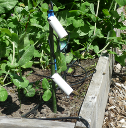
The SODA was placed in an enclosure and the setup was placed in a raised bed with sensors both in the air and in the soil. PVC pipe was cut long-wise to use as quick-and-dirty radiation shield.
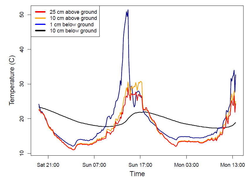
The data were interesting after only a couple of days. The sensor just below the ground surface became very warm during the middle of the day and the diurnal range of the sensor buried 10 cm below surface was greater than I expected. The neat thing about this setup is that you could easily add many more sensors: 10, 20, 30 or more, and still have room for other sensors!